


Power as the "heart" of the circuit system, its importance is obvious. In the choice of power module, in addition to consider the input voltage range, rated power, isolation voltage, efficiency, ripple & noise and other performance characteristics, but also for its high and low temperature performance and derating design reliability test.
Power can be said that the circuit system "heart", for the various levels of circuit to provide "blood", its importance is obvious. So how to effectively choose a high-performance high-reliability power module? We will first focus on the power module input voltage range, rated power, isolation voltage, efficiency, ripple & noise input and output characteristics, to determine whether to meet their own requirements, even with reference to the data manual one by one test the indicators to determine Whether it is consistent with the claim. But for the reliability of the power module, the completion of these is still far from enough, there are two aspects that need to dig deep test, that is, high and low temperature performance and derating design.
1、high and low temperature performance
High and low temperature test is used to determine the product in the low temperature, high temperature two extreme climatic conditions and adaptability and consistency, check the design margin is sufficient. Because the characteristics of components in the low temperature, high temperature conditions will be a certain change, the performance parameters with temperature drift characteristics. So often a lot of power modules at room temperature through the test, once you get high and low temperature test found that the work is not normal or performance parameters decreased significantly. At the same time through a long time high temperature aging can make components defects, welding and assembly and other production processes exist in advance of the hidden danger.
Power module common low temperature and high temperature bad phenomenon:
(1) Oscillation of the output, the output voltage ripple and noise become larger, the frequency changes, and even the output voltage jumps, the module whistles.
(2) poor start, such as the output voltage rise when the waveform has obvious ditch, the output voltage is unstable, or even complete failure of the module.
(3) with capacitive load capacity weakened, can not bring the maximum capacitive load start.
(4) When the output voltage overshoot increases, beyond the specified range.
(5) overload or full load operation when the output voltage is significantly reduced.
(6) high temperature aging damage, the module is not output.
Therefore, the high reliability of the power supply module must ensure that the high and low temperature and other extreme conditions to work properly to meet the performance requirements.
2、derating design
The derating design is to derive the components, that is, the working stress of the electronic components is appropriately lower than its specified rating, the derating of the device can delay and reduce its degradation and improve the reliability of the device, thus Also improved the reliability of the module. The failure rate of electronic components is more sensitive to voltage stress, current stress and temperature stress, so the derating design is mainly for these three aspects. The derating level of electronic components can refer to the "national military standard - component derating criterion GJB / Z35-93", generally can be divided into three derating levels:
(1) Class I derating: Class I derating is the maximum derating and applies to equipment failure that would compromise safety, resulting in failure of the task and serious economic losses.
(2) Class II derating: The decrease in working stress has a significant benefit to the reliability growth of components. Applies to equipment failure will degrade the work tasks or pay unreasonable maintenance costs.
(3) Class III derating: Class III derating is the minimum derating, relatively speaking, the cost of components is also low. Applicable to equipment failure has little effect on the completion of the task, or can be repaired promptly and economically.
For the power module stress design, focusing on the field effect transistor (MOS tube), diodes, transformers, power inductors, electrolytic capacitors, current limiting resistors and so on. To ensure that the full voltage range in the steady state, transient, short circuit and other extreme conditions can have enough derating to protect the reliability of the product. For example, for a VDS maximum voltage of 100V MOS tube, as the power module of the main power switch, measured at the highest input voltage under various states (shown in Figure 1 ~ 3), the highest Vds = 67.2V, derating Factor 0.672, to meet the level Ⅰ derating, the margin is sufficient.

Figure 1 steady-state working MOS tube waveform Vds_max = 57.2V

Figure 2 output short circuit when the MOS tube waveform Vds_max = 67.2V

Figure 3 when the machine starts transient MOS tube waveform Vds_max = 59V
As the power module tends to be miniaturized, the power density is getting higher and higher, and the power module is particularly problematic in terms of thermal design. In particular, the use of electrolytic capacitors with the power module, high temperature electrolytic capacitors will accelerate the consumption of electrolytes, electrolytic capacitors greatly reduce the life. High temperature will make the component material to accelerate aging, for example, make the transformer enameled wire insulation characteristics reduced, resulting in poor insulation voltage and even short-circuit between the inter-turn. So good thermal design can not only extend the power module and its surrounding components of the service life, but also make the whole product heat evenly to reduce the occurrence of failure.
Power module thermal design of the basic tasks are: through the thermal design to meet the performance requirements under the premise of minimizing the heat generated within the module to reduce heat resistance, choose a reasonable cooling method. Heating components to make it as much as possible to disperse the layout. Design PCB board to ensure that the current carrying capacity of the printed circuit, the width of the printed line must be suitable for current conduction. For high-power chip components, you can use a large area of copper foil way to increase the PCB cooling area. The inside of the power module can reduce the temperature rise of the internal components of the module by filling the thermal silica gel and the resin. Harvatek For larger power modules, heat dissipation can be used to increase the surface area of convection and radiation, which greatly improves the heat dissipation of electronic devices.
For the power module without potting, you can use the infrared thermal imager on the entire power module "surface" temperature measurement, infrared thermal imager is the object of the invisible infrared energy into a visible thermal image. The different colors above the thermal image represent the different temperatures of the measured object. And then through the analysis, and then use the thermocouple with data collection equipment focus on the MOS tube, rectifier diodes, transformers and other key components of the temperature of the "point" of the temperature. From surface to point, rigorous testing to ensure that the components of the temperature derating to meet the requirements.
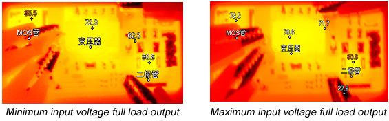
Figure 4 Thermal imaging of a power module at room temperature
For example, for a power module, after a long period of time working with infrared thermal imager to test the surface temperature shown in Figure 4, which MOS tube at room temperature is not potting the maximum temperature of 85.5 ℃, and then use the thermocouple with data acquisition instrument Filled with potting of finished products in high temperature conditions to test the temperature in various circumstances, up to 97.2 ℃, for the maximum temperature of 175 ℃ MOS tube, the temperature derating to meet the level Ⅰ derating.
So in addition to the basic performance parameters test, a comprehensive high and low temperature test, electrical stress and thermal stress test to ensure adequate derating design requirements, and through a long time aging test, can determine whether the power supply module is safe and reliable. ZLG Zhiyuan electronic independent research and development of power modules, are through strict derating design and comprehensive high and low temperature test, product performance and reliability of adequate protection. For example, the above example is the Division I E_UHBD-15W series of a part of the test data, the series of products input voltage range, high efficiency, low temperature, stable and reliable, widely used in industrial control, power, communications, Instrumentation and automotive electronics and many other fields.