

The electric vehicle inverter is used to control the main motor of the automobile to provide power for the operation of the automobile. The IGBT power module is the core power device of the inverter of the electric vehicle. The drive circuit is the key circuit for the performance of the IGBT. The design of the drive circuit has more stringent technical requirements for the drive circuits of industrial general-purpose inverters and wind energy solar inverters. Among them, the power supply circuit is limited by a small space size, a high operating temperature, and faces many challenges.
This paper designs a driving power supply and proves its availability through practical tests. The common driving power is designed using a flyback circuit and a transformer with multiple primary sides and one side. Since the flyback power supply provides the inherent characteristics of energy output to the load during the off period of the switch, its current output characteristics and transient control characteristics are relatively poor. In the IGBT module space layout of the order of 100kW, the design of a single transformer to produce 4 to 6 mutually isolated positive and negative power supplies has many drawbacks: the power is too concentrated, the creepage distance and clearance are difficult to guarantee, and the power supply distance on the board Too long and so on. This design adopts a common non-dedicated chip for circuit design. The front-end SEPIC circuit realizes closed-loop, and the latter-stage half-bridge circuit achieves isolation to effectively solve the above problems. The circuit was successfully applied in the international leading inverter design for new energy vehicles. The application shows that the design has good flexibility, high reliability and transient response capabilities.
1. Analysis of Requirements for Driving Inverters of Electric Vehicles
Electric vehicle inverter drive power is generally 6 isolated +15V/-5V power supply. The power supply, electrical isolation capability, peak current capability, operating temperature, etc., all have stringent requirements. The Infineon's automotive-grade IGBT module FS800R07A2E3_B31 is targeted at the specific calculation of the power supply target. This module supports up to 150kW inverter system design.
1.1 Drive Power Calculation
The input power calculation formula of this driving power is:
P=f_sw&TImes;Q_g&TImes;ΔV_g/η (1)
Which f_sw switching frequency to take 10kHz, Q_g according to the datasheet to take 8.6nC, △V_g for the gate drive voltage to take 23V. Considering the small power, the efficiency is taken as 85%. Also note that the 8.6nC in the data sheet is based on a voltage of +/-15V and needs to be considered. The final calculation is 1.8W. Consider design margin 1.1 times, denoted as 2W.
1.2 Drive Current Calculation
The average driving current calculation formula is:
I_av=f_sw&TImes;Q_g (2)
The average current can be calculated to 86mA.
The peak current calculation formula is:
I_peak=ΔV_g/(R_gext+R_gint) (3)
R_gext is the external sector resistance, according to the data manual to open the 1.8 Europe off 0.75 ohm. R_gint is the internal gate resistor. According to the data sheet, 0.5 ohm is used to obtain the peak current of 10A and the peak current of 18.4A. In actual use, the on-resistance and off-resistance need to be traded for performances such as switching speed and short-circuit protection capability. A good design value is in the range of 2.2 to 5.1 ohms, so the actual switch peak current is in the range of 4 to 10A.
2.drive power circuit design
2.1 Power Supply Topology Design
The input of the power supply is the conventional 12V power supply for the new energy passenger vehicle. The power supply usually has a fluctuation range of 8~16V, and the output of the driving power supply needs to be relatively stable. It is necessary to design multiple isolated power supplies with wide voltage input and constant voltage output. This design divides the power supply into two levels: the pre-stage power supply realizes the wide voltage input and constant voltage output functions, and the subsequent stage realizes the isolation function. The structure is shown in Figure 1.
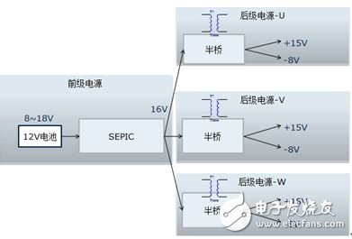
Figure 1: Power topology
The advantages of this structure are:
First, the pre-level power supply does not need to solve the isolation problem, you can use a conventional SEPIC or buck-boost non-isolated topology, and the output of the pre-stage power supply is a low-voltage constant voltage that does not need to be isolated. There is no need to consider the creepage between each group of power supplies in the layout and wiring. Distance and clearance problems. Therefore, this part of the pre-stage can be independently implemented as a low-voltage weak current circuit without occupying the area of the driver board.
Second, after the power supply does not need to solve the feedback problem, open-loop control is adopted to avoid the trouble of isolating signal feedback. Because of poor working conditions of passenger car equipment, the operating temperature range is very large, the traditional linear optocoupler and other devices are greatly affected by temperature drift, precision, temperature drift compensation device and high cost, this way to effectively avoid this drawback.
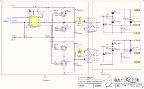
2.2 After-class half-bridge switching power supply design
The pre-stage power supply is a typical constant voltage design and does not require design principles. This article focuses on the post-stage half-bridge circuit. Specific schematics are shown in Figure 2 and Figure 3. Figure 2 shows a 50% duty cycle signal generator designed with an automotive timer circuit to provide a control signal to the half-bridge switching power supply. R49 can be used to adjust the switching frequency. It can be set between 70kHz and 300kHz. Frequency selection is mainly based on the actual space size of the circuit board and the volt-second product of the transformer.
The formula for calculating the volt-second product from the transformer is:
ET=V*D/f_sw (4)
V is the voltage applied to the transformer, D is the duty cycle, and f_sw is the switching frequency. This design selects a transformer with an ET value of 44 Vusec, so the switching frequency is set to 120 kHz.
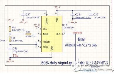
Figure 2: 50% duty cycle signal generation circuit
Figure 3 shows the half-bridge switching power supply circuit. This circuit uses an IR automotive-grade half-bridge chip IRS2004S as a driver and two parallel-connected half-bridge circuits consisting of Infineon BSR302N. Using a universal transformer with turns ratio of 1:1.25, a voltage of +15V is obtained after voltage doubler rectification, and -8V voltage is obtained through ordinary rectification. Each transformer is used to power an IGBT module driver. Inserting the automotive EMC magnetic beads in series with the primary side of the transformer can effectively suppress the voltage spikes generated by the switches. See Appendix Table 1 for specific device information. The IGBT gate is a capacitive load. Each switch is accompanied by a high transient current, which is the peak drive current calculated earlier. Therefore, a long-life capacitor with strong ripple current capability is required. Each channel uses 4.7uF. X7R automotive grade multilayer ceramic capacitors for transient voltage support. The X7R multilayer ceramic capacitor has the advantages of small package, low ESR, allowing large ripple current, reduced temperature, and reduced capacity decay.