


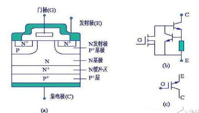
IGBT (Insulated Gate Bipolar Transistor), an insulated gate bipolar transistor, is a compound fully-controlled voltage-driven power semiconductor device consisting of BJT (bipolar transistor) and MOS (insulated gate field effect transistor) The advantages of high input impedance and low turn-on voltage drop of the GTR. The GTR has lower saturation voltage, higher current density, but higher drive current. The MOSFET has low drive power and fast switching speed, but has large turn-on voltage drop and low current density. IGBTs combine the advantages of the above two devices, with low drive power and reduced saturation pressure. It is very suitable for converter systems with DC voltages of 600V and above, such as AC motors, frequency converters, switching power supplies, lighting circuits, and traction drives.
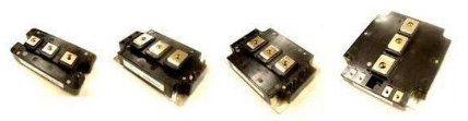
The IGBT module is a modular semiconductor product formed by IGBT (insulated gate bipolar transistor chip) and FWD (freewheeling diode chip) through a specific circuit bridge package; packaged IGBT module directly applied to the inverter, UPS uninterrupted Power supply and other equipment; IGBT module has the characteristics of energy saving, easy installation and maintenance, stable heat dissipation, etc.; most of the current market sales are such modular products, generally speaking IGBT also refers to IGBT module; with the promotion of concepts such as energy saving and environmental protection This type of product will become more and more common in the market; IGBT is the core device for energy conversion and transmission, commonly known as the "CPU" of power electronic devices, as a national strategic emerging industry, in rail transit, smart grid, aerospace, The application of electric vehicles and new energy equipment is extremely wide.
IGBT operating characteristics:
Static characteristics of IGBT
Static characteristics mainly include volt-ampere characteristics, transfer characteristics, and switching characteristics.
(1) Volt-ampere characteristics:
The volt-ampere characteristic of the IGBT refers to the relationship between the drain current and the gate voltage when the gate-source voltage Ugs is used as a parameter. The output drain current ratio is controlled by the gate-source voltage Ugs. The higher Ugs, the larger Id. It is similar to the output characteristics of the GTR. It can also be divided into saturation zone 1, amplification zone 2, and breakdown characteristics 3. In the off-state IGBT, the forward voltage is borne by the J2 junction and the reverse voltage is borne by the J1 junction. If there is no N+ buffer, then the forward and reverse blocking voltages can be set to the same level. After the N+ buffer is added, the reverse turn-off voltage can only reach several tens of volts, thus limiting the IGBT's application range.
(2) transfer characteristics:
The transfer characteristic of the IGBT refers to the relationship between the output drain current Id and the gate-source voltage Ugs. It has the same transfer characteristics as the MOSFET. When the gate-to-source voltage is less than the turn-on voltage Ugs(th), the IGBT is turned off. In most of the drain current range after IGBT is turned on, Id has a linear relationship with Ugs. The maximum gate-source voltage is limited by the maximum drain current, and its optimum value is generally about 15V.
(3) Switch effects:
The switching characteristics of an IGBT refer to the relationship between the drain current and the drain-source voltage. When the IGBT is in the on-state, its B-value is extremely low because its PNP transistor is a wide-base transistor. Although the equivalent circuit is a Darlington structure, the current flowing through the MOSFET becomes a major part of the total IGBT current. At this time, the on-state voltage Uds(on) can be represented by
Uds(on) = Uj1 + Udr + IdRoh
Where Uj1 is the forward voltage of the JI junction and its value is 0.7 to 1V; Udr is the voltage drop across the extended resistor Rdr; Roh is the channel resistance.
The on-state current Ids can be expressed by the following formula:
Ids=(1+Bpnp)Imos
Imos - the current flowing through the MOSFET.
Due to the conductance modulation effect in the N+ region, the IGBT has a low on-state voltage drop, and the on-state voltage drop of a 1000V IGBT is 2 to 3V. When the IGBT is in the off state, only a small leakage current exists.
IGBT dynamic characteristics
Most of the IGBTs are operated as MOSFETs during the turn-on process. Only during the late stage of the drain-source voltage Uds reduction process, the PNP transistors are enlarged from the amplification area to add a delay time. Td(on) is the turn-on delay time, and tri is the current rise time. The drain current turn-on time, often given in practical applications, is the sum of td (on) tri. The fall time of the drain-source voltage consists of tfe1 and tfe2.
The triggering and turning-off of the IGBT requires that a forward voltage and a negative voltage be applied between the gate and the base, and the gate voltage can be generated by different driving circuits. When selecting these driver circuits, it must be based on the following parameters: device off bias requirements, gate charge requirements, resistance requirements, and power supply conditions. Because the gate-emitter impedance of the IGBT is large, it can be triggered using MOSFET drive technology, but since the input capacitance of the IGBT is larger than that of the MOSFET, the turn-off bias of the IGBT should be higher than that provided by many MOSFET drive circuits.
During the turn-off process of the IGBT, the waveform of the drain current becomes two stages. Because the MOSFET is turned off, the stored charge of the PNP transistor is difficult to eliminate quickly, resulting in a tail time with a long drain current, td(off) is the turn-off delay time, and trv is the rise time of the voltage Uds(f). The drop time Tf of the drain current often given in practical applications is composed of two sections t(f1) and t(f2) in the figure, and the off-time of the drain current.
t(off)=td(off)+trv ten t(f)
In the formula, the sum of td(off) and trv is also called storage time.
The switching speed of IGBTs is lower than that of MOSFETs, but it is significantly higher than GTR. The IGBT does not require a negative gate voltage to turn off the turn-off time when turned off, but the turn-off time increases as the parallel resistance of the gate and emitter increases. The IGBT's turn-on voltage is about 3 to 4V, which is comparable to that of a MOSFET. The saturation voltage drop when the IGBT is turned on is lower than that of the MOSFET and close to the GTR, and the saturation voltage drop decreases as the gate voltage increases.
IGBT judgment test:
Judgment polarity:
First, set the multimeter to R&TImes; 1KΩ. When measuring with a multimeter, if the resistance of one pole and the other is infinite, change the resistance of the pole and other two poles after the test is still infinite, determine the gate (G ) The remaining two poles are then measured with a multimeter. If the measured resistance is infinite, change the meter to measure the resistance. In the measurement of a small resistance value, it is determined that the red pencil is a collector (C); the black pencil is an emitter (E).
Good or bad judgment:
Put the multimeter on the R&TImes; 10KΩ, and connect the collector of the IGBT (C) with a black lead. Connect the red lead to the emitter of the IGBT (E). The multimeter's pointer is at zero. Touching the gate (G) and the collector (C) at the same time with your finger, the IGBT is triggered to conduct. The pointer of the multimeter swings to a direction with a smaller resistance and can stand in a certain position. Then touch the gate (G) and emitter (E) at the same time with your finger. The IGBT is then blocked and the multimeter's hand is homed. At this point, it can be judged that the IGBT is good.
Testing notes:
Any analog multimeter can be used to detect IGBTs. Note that when judging the IGBT is good or bad, be sure to set the multimeter to R&TImes; 10KΩ, because R&TImes; 1KΩ, the internal voltage of the battery in the multimeter is too low, the IGBT cannot be turned on when the test is good or bad, and it is impossible to judge the quality of the IGBT. . This method can also be used to detect the quality of power MOSFETs (P-MOSFETs).